Products
- Auto Switches[1]
- Computer Cables & Connectors[1]
- Card Readers[1]
- Memory Cards[4]
- Other Accessories & Parts[1]
- Connectors[3]
- Fuses[1]
- Inductors[10]
- Relays[5]
- Limit Switches[1]
- Push Button Switches[3]
- Rocker Switches[2]
- Slide Switches[1]
- Diodes[10]
- Integrated Circuits[10]
- Oscillators[8]
- Other Active Components[6]
- Rectifiers[8]
- Transistors[10]
- Electronics Stocks[1]
- LCD Modules[3]
- LED Displays[3]
- Other Optoelectronic Displays[1]
- Other Electronic Components[10]
- Capacitors[10]
- Other Passive Components[1]
- Resistors[10]
- Other Lights & Lighting Products[4]
- CCTV Camera[10]
- Other Security & Protection Products[2]
- Other Mobile Phone Accessories[1]
Contact Us
- Contact Person : Mr. Lee Michael
- Company Name : Shenzhen Canyi Technology Co., Ltd.
- Tel : 0086-755-83740245
- Fax : 0086-755-83740361
- Address : Guangdong,shenzhen,Room 1319, Jia Hui Building, Fuhua Road, Futian District
- Country/Region : China
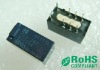
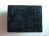
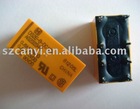
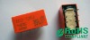
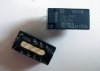
relay TX2-24V


Product Detailed
TX2-24V
CAPACITY RELAY WITH HIGH SURGE VOLTAGE HIGH BREAKDOWN VOLTAGE
datasheet available upon request
TESTING2 A CAPACITY RELAY WITH HIGH SURGE VOLTAGE & HIGH BREAKDOWN VOLTAGE15 .591 7.4 .291 8.2 .323 15 .591 7.4 .291 8.4 .331TX RELAYSFEATURES* Breakdown voltage between contacts and coil: 2,000 V * Surge withstand between contacts and coil: 2,500 V * High contact capacity: 2 A 30 V DC * Surface-mount type availablemm inchSPECIFICATIONSContactArrangement Initial contact resistance, max. (By voltage drop 6 V DC 1 A) Contact material Nominal switching capacity (resistive load) Max. switching power (resistive load) Rating Max. switching voltage Max. switching current Min. switching capacity 1 Nominal operating power Single side stable 1 coil latching 2 coil latching Mechanical (at 180 cpm) 2 A 30 V DC resistive Electrical (at 20 cpm) 1 A 30 V DC resistive 2 Form C 100 m Gold-clad silver alloy 2 A 30 V DC 60 W 220 V DC 2A 10 A 10 mV DC 140 mW (1.5 to 24 V DC) 270 mW (48 V DC) 100 mW (1.5 to 24 V DC) 200 mW (1.5 to 24 V DC) 108 105 5x10⁵CharacteristicsInitial insulation resistance*1 Between open contacts Initial breakdown Between contact sets voltage Between contact and coil Between open contacts Initial surge (10x160 s) voltage Between contacts and coil (2x10 s) Temperature rise*2 (at 20C) Min. 1,000 M (at 500 V DC) 1,000 Vrms for 1 min. (Detection current: 10 mA) 1,000 Vrms for 1 min. (Detection current: 10 mA) 2,000 Vrms for 1 min. (Detection current: 10 mA) 1,500 V (FCC Part 68) 2,500 V (Telcordia) Max. 50CExpected life (min. operations) Notes:1This value can change due to the switching frequency, environmental conditions, and desired reliability level, therefore it is recommended to check this with the actual load. (SX relays are available for low level load switching [10 A 1 mV DC - 10 mA 10 V DC]) 2The upper limit for the ambient temperature is the maximum temperature that can satisfy the coil temperature rise. Under the packing condition, allowable temperature range is from -40 to +70C -40C to +158F.Remarks* Specifications will vary with foreign standards certification ratings. *1 Measurement at same location as "Initial breakdown voltage" section. *2 By resistive method, nominal voltage applied to the coil; contact carrying current: 2 A. *3 Nominal voltage applied to the coil, excluding contact bounce time. 4 Nominal voltage applied to the coil, excluding contact bounce time without diode. * *5 Half-wave pulse of sine wave: 6 ms; detection time: 10 s. *6 Half-wave pulse of sine wave: 6 ms. *7 Detection time: 10 s. *8 Refer to 6. Conditions for operation, transport and storage mentioned in AMBIENT ENVIRONMENT.Max. 4 ms (Approx. 2 ms) Operate time [Set time]*3 (at 20C) [Max. 4 ms (Approx. 2 ms)] Max. 4 ms (Approx. 1 ms) Release time [Reset time]*4 (at 20C) [Max. 4 ms (Approx. 2 ms)] Min. 750 m/s2 {75 G} Functional*5 Shock resistance Destructive*6 Min. 1,000 m/s2 {100 G} 196 m/s2 {20 G}, 10 to 55 Hz Functional*7 at double amplitude of 3.3 mm Vibration resistance 294 m/s2 {30G}, 10 to 55 Hz Destructive at double amplitude of 5 mm -40C to +85C (up to 24 V coil) Conditions for operation, transport and Ambient tem- -40F to +185F (up to 24 V coil) perature 2 -40C to +70C (48 V coil) storage*8 (Not freezing and -40F to +158F (48 V coil) condensing at low Humidity 5 to 85% R.H. temperature) Unit weight Approx. 2 g .071 ozTXORDERING INFORMATIONEx. TX Contact arrangement 2: 2 Form C Surface-mount availability Nil: Standard PC board terminal type or Nil: self-clinching terminal type SA: Standard surface-mount terminal type SL : High connection reliability surface-mount SL : terminal type SS: Space saving surface-mount terminal type 2 SAZ Packing styleOperating function Terminal shape Nil: Single side Nil: stable L: 1 coil latching L2: 2 coil latchingCoil voltage (DC)Nil: Standard PC 1.5, 3, 4.5, 5, 6, Nil: Tube packing board terminal or 9, 12, 24, 48* V Z: Tape and reel surface-mount packing(picked terminal from the 8/9/10/12 H: Self-clinching -pin side terminal Notes: 1. Tape and reel (picked from 1/3/4/5-pin side) is also available by request. Part number suffix "-X" is *48 V coil type: Single side stable onlyneeded when ordering. (ex.) TX2SA-3 V-X 2. Tape and reel packing symbol "-Z" or "-X" are not marked on the relay.TYPES AND COIL DATA (at 20C 68F)1) Standard PC board terminal type and self-clinching terminal type 1. Single side stablePart No. Standard PC board terminal TX2-1.5 V TX2-3 V TX2-4.5 V TX2-5 V TX2-6 V TX2-9 V TX2-12 V TX2-24 V TX2-48 V Self-clinching terminal TX2-H-1.5 V TX2-H-3 V TX2-H-4.5 V TX2-H-5 V TX2-H-6 V TX2-H-9 V TX2-H-12 V TX2-H-24 V TX2-H-48 V Nominal voltage, V DC 1.5 3 4.5 5 6 9 12 24 48 Pick-up voltage, V DC (max.) 1.13 2.25 3.38 3.75 4.5 6.75 9 18 36 Drop-out voltage, V DC (min.) 0.15 0.3 0.45 0.5 0.6 0.9 1.2 2.4 4.8 Nominal operating current, mA (10%) 93.8 46.7 31 28.1 23.3 15.5 11.7 5.8 5.6 Coil resistance, (10%) 16 64.3 145 178 257 579 1,028 4,114 8,533 Nominal operating power, mW 140 140 140 140 140 140 140 140 270 Max. allowable voltage, V DC 2.2 4.5 6.7 7.5 9 13.5 18 36 57.62. 1 Coil latchingPart No. Standard PC board terminal TX2-L-1.5 V TX2-L-3 V TX2-L-4.5 V TX2-L-5 V TX2-L-6 V TX2-L-9 V TX2-L-12 V TX2-L-24 V Self-clinching terminal TX2-L-H-1.5 V TX2-L-H-3 V TX2-L-H-4.5 V TX2-L-H-5 V TX2-L-H-6 V TX2-L-H-9 V TX2-L-H-12 V TX2-L-H-24 V Nominal voltage, V DC 1.5 3 4.5 5 6 9 12 24 Set voltage, V DC (max.) 1.13 2.25 3.38 3.75 4.5 6.75 9 18 Reset voltage, V DC (max.) 1.13 2.25 3.38 3.75 4.5 6.75 9 18 Nominal operating current, mA (10%) 66.7 33.3 22.2 20 16.7 11.1 8.3 4.2 Coil resistance, (10%) 22.5 90 202.5 250 360 810 1,440 5,760 Nominal operating power, mW 100 100 100 100 100 100 100 100 Max. allowable voltage, V DC 2.2 4.5 6.7 7.5 9 13.5 18 363. 2 Coil latchingPart No. Standard PC board terminal TX2-L2-1.5 V TX2-L2-3 V TX2-L2-4.5 V TX2-L2-5 V TX2-L2-6 V TX2-L2-9 V TX2-L2-12 V TX2-L2-24 V Notes: Self-clinching terminal TX2-L2-H-1.5 V TX2-L2-H-3 V TX2-L2-H-4.5 V TX2-L2-H-5 V TX2-L2-H-6 V TX2-L2-H-9 V TX2-L2-H-12 V TX2-L2-H-24 V Nominal voltage, V DC 1.5 3 4.5 5 6 9 12 24 Set voltage, V DC (max.) 1.13 2.25 3.38 3.75 4.5 6.75 9 18 Reset voltage, V DC (max.) 1.13 2.25 3.38 3.75 4.5 6.75 9 18 Nominal operating current, mA (10%) 133.9 66.7 44.5 40 33.3 22.2 16.7 8.3 Coil resistance, (10%) 11.2 45 101.2 125 180 405 720 2,880 Nominal operating power, mW 200 200 200 200 200 200 200 200 Max. allowable voltage, V DC 2.2 4.5 6.7 7.5 9 13.5 18 36
relay TX2-24V
Other products